Quick answer
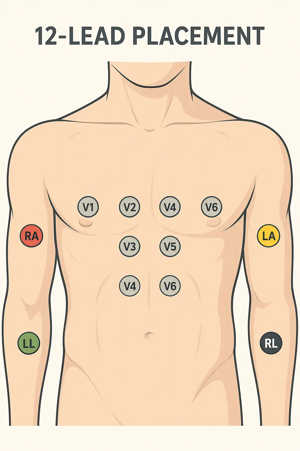
A standard 12-lead ECG uses 10 electrodes: four limb leads (RA, LA, RL, LL) and six chest leads (V1–V6). V1 sits at the fourth intercostal space to the right of the sternum, V2 at the fourth intercostal space to the left, V4 at the fifth intercostal space on the midclavicular line, V3 midway between V2 and V4, V5 at the anterior axillary line level with V4, and V6 at the midaxillary line level with V4. Place V4 before V3.
Who this guide is for: clinical and biomedical staff placing electrodes for diagnostic ECG, and equipment teams supporting them. It covers electrode placement and the accessories involved.
12-Lead ECG Electrode Placement Quick Reference
A diagnostic 12-lead ECG (also commonly written EKG) uses 10 electrodes to create 12 views of the heart. Use this table for a fast bedside check, then follow the step-by-step sections below for landmarks and technique.
| Electrode |
Placement |
| RA |
Right arm, between the shoulder and wrist |
| LA |
Left arm, between the shoulder and wrist |
| RL |
Right leg or lower torso (ground electrode) |
| LL |
Left leg or lower torso |
| V1 |
4th intercostal space, right sternal border |
| V2 |
4th intercostal space, left sternal border |
| V4 |
5th intercostal space, midclavicular line |
| V3 |
Midway between V2 and V4 (place V4 first) |
| V5 |
Same horizontal level as V4, anterior axillary line |
| V6 |
Same horizontal level as V4 and V5, midaxillary line |
Practical placement sequence: limb electrodes first (RA, LA, RL, LL), then chest electrodes in this order: V1 → V2 → V4 → V3 → V5 → V6. V3 cannot be placed accurately until V4 is located.
| Electrode |
Anatomical landmark |
AAMI colour |
IEC colour |
| RA |
Right arm, between the shoulder and wrist |
White |
Red |
| LA |
Left arm, between the shoulder and wrist |
Black |
Yellow |
| RL |
Right leg or lower torso (ground) |
Green |
Black |
| LL |
Left leg or lower torso |
Red |
Green |
| V1 |
4th intercostal space, right sternal border |
Red |
Red |
| V2 |
4th intercostal space, left sternal border |
Yellow |
Yellow |
| V3 |
Midway between V2 and V4 (place V4 first) |
Green |
Green |
| V4 |
5th intercostal space, midclavicular line |
Blue |
Brown |
| V5 |
Same horizontal level as V4, anterior axillary line |
Orange |
Black |
| V6 |
Same horizontal level as V4 and V5, midaxillary line |
Purple |
Purple |
Limb and chest colours follow the AAMI and IEC lead colours used in this site’s colour reference. Precordial colours can vary by manufacturer within each standard — confirm the labelling on the lead set in hand.
Why Accurate 12-Lead Placement Matters
A 12-lead ECG records electrical activity from 12 different perspectives using 10 electrodes. These leads allow clinicians to evaluate cardiac rhythm, conduction, chamber enlargement, ischemia, and infarction.
Because each lead offers a unique view of the heart's electrical activity, standardization is vital. Even small placement deviations can lead to:
- Axis shifts that mimic pathologies
- Altered R-wave progression suggesting infarction
- Pseudo-infarct patterns (e.g., false anterior STEMI)
- Masking of real ischemic changes
For institutions committed to patient safety, ensuring all staff know and follow correct placement is non-negotiable.
Understanding the 12 Leads: A Clinical Overview
The 12-lead ECG consists of:
- 4 limb electrodes: RA, LA, RL, LL
- 6 precordial (chest) electrodes: V1–V6
Limb leads create six views of the heart's electrical activity in the frontal plane:
- Leads I, II, III (bipolar)
- aVR, aVL, aVF (augmented)
Precordial leads (V1–V6) provide horizontal plane views. In broad clinical terms:
- Septal / anterior views: V1–V4
- Lateral views: I, aVL, V5, V6
- Inferior views: II, III, aVF
This multi-view perspective is why a correctly placed 12-lead ECG is central to detecting ischemic changes.
Patient Positioning and Preparation
For a diagnostic resting 12-lead, position the patient supine (lying on the back) with arms relaxed at the sides when clinically appropriate. Expose the chest and limbs enough to reach anatomical landmarks without forcing electrodes onto clothing or folds of skin.
Skin preparation belongs with placement, not after a noisy tracing appears:
- Clean the skin with alcohol wipes.
- Remove oils, sweat, or lotions.
- Shave hair if needed.
- Let alcohol dry before electrode placement.
- Use fresh, quality electrodes.
Securing Cables: Loop and tape cables to reduce movement artifacts, especially in restless or transported patients.
Limb Lead Placement: The Foundation
Correct limb lead placement may seem simple but is often done incorrectly. It forms the basis for the frontal plane axis and needs consistency.
- RA (Right Arm): Between shoulder and wrist on the right arm.
- LA (Left Arm): Between shoulder and wrist on the left arm.
- RL (Right Leg): Anywhere on the right leg or lower torso. Serves as the ground electrode.
- LL (Left Leg): Left leg or lower torso.
Best Practice: Place limb electrodes distally (forearms and calves) for diagnostic ECGs. For continuous monitoring (e.g., ICU), torso placements—sometimes called Mason-Likar torso placement—may be acceptable, but always document the modification because waveform morphology can change versus distal limb placement.
Clinical Tip: Ensure skin is dry and free from lotions. Shave if necessary to improve adhesion.
Precordial Lead Placement: Step-by-Step Guide
Chest leads are the most error-prone. Place them in this order: V1, V2, V4, V3, V5, V6.
V1 and V2
- Locate the sternal angle (Angle of Louis) to find the 2nd rib.
- Count down to the 4th intercostal space.
- V1: Right sternal border.
- V2: Left sternal border.
Pitfall to Avoid: Placing V1 and V2 too high (3rd ICS) or too low (5th ICS) alters septal waveforms.
V4 (place before V3)
- 5th intercostal space at the midclavicular line.
- Palpate the clavicle and ensure alignment.
Tip: Watch for breast tissue—move as needed to ensure direct chest wall contact.
V3
- Place midway between V2 and V4 after V4 is located.
- Don't guess; measure carefully.
Clinical Insight: V3 is critical for seeing anterior changes. Incorrect placement can obscure ST elevation.
V5
- Horizontally level with V4.
- Anterior axillary line.
Common Error: Placing too anterior or posterior—compromises lateral lead views.
V6
- Same level as V4 and V5.
- Midaxillary line.
Pro Tip: Check horizontal alignment. A crooked line across V4–V6 distorts interpretation.
3-Lead and 5-Lead Monitoring Placement
Continuous bedside monitoring is not the same as a diagnostic 12-lead ECG. Monitoring configurations use fewer electrodes, display fewer simultaneous views, and typically place those electrodes on the torso rather than on the distal limbs so that arm and leg movement does not tug the tracing.
A 3-lead configuration uses three electrodes — RA, LA, and LL — usually on the right and left infraclavicular areas and the lower left torso. The monitor can display one bipolar limb lead at a time (commonly lead II). It is a rhythm-monitoring setup, not a diagnostic 12-lead.
A 5-lead configuration adds RL (right-leg / ground, typically on the lower right torso) and one chest electrode, most often at the V1 landmark. That arrangement can display any of the six frontal-plane leads (I, II, III, aVR, aVL, aVF) plus the selected chest lead. It still does not replace a diagnostic 12-lead ECG.
Monitoring placement is torso-based because distal limb electrodes pick up muscle artifact during movement. Document the modification when a tracing recorded from torso positions is compared with a standard diagnostic 12-lead.
10-Lead vs 12-Lead: Why the Numbers Differ
A standard “12-lead ECG” is recorded with ten electrodes. Four limb electrodes and six chest electrodes produce twelve views of the heart because six of those views are calculated rather than wired as separate electrodes.
The four limb electrodes (RA, LA, RL, LL) generate the six frontal-plane leads: I, II, III, aVR, aVL, and aVF. RL is the ground. The six chest electrodes (V1–V6) record the six precordial leads directly. The extra two “leads” in the name 12-lead are derived from the limb electrode set — they are not extra stickers on the patient.
That is why product listings, cable sets, and clinical conversation can disagree: a 10-leadwire cable is the usual accessory for a diagnostic 12-lead acquisition. The terminology is confusing until electrode count and derived-lead count are separated.
| Name |
Electrodes on the patient |
Leads displayed |
| 3-lead monitoring |
3 (RA, LA, LL) |
One bipolar limb lead at a time (I, II, or III) |
| 5-lead monitoring |
5 (RA, LA, RL, LL, one V) |
Frontal-plane leads plus one chest lead |
| 12-lead diagnostic ECG |
10 (RA, LA, RL, LL, V1–V6) |
12 views: I, II, III, aVR, aVL, aVF, V1–V6 |
Posterior Lead Placement (V7, V8, V9)
Posterior leads continue the V6 horizontal line around the left chest wall. They are recorded when a posterior view is required in addition to the standard 12-lead — most often when posterior infarction is a clinical concern and standard precordial leads are inconclusive.
- V7: same horizontal level as V6, left posterior axillary line.
- V8: same horizontal level, left midscapular line.
- V9: same horizontal level, left paraspinal region.
They are additional positions, not a replacement for V1–V6. Follow facility protocol for when to acquire a posterior ECG and how to label the tracing.
Right-Sided Lead Placement (V3R–V6R)
Right-sided chest leads mirror the standard V positions on the right chest wall. They are used when a right-ventricular view is required in addition to the standard 12-lead.
- V3R: midway between V1 and V4R, mirroring the V3 relationship on the right.
- V4R: fifth intercostal space, right midclavicular line (the right-sided counterpart of V4).
- V5R: same horizontal level as V4R, right anterior axillary line.
- V6R: same horizontal level as V4R, right midaxillary line.
V4R is the right-sided position most often added in practice. Standard V1–V6 remain the reference; V3R–V6R are extra positions, not a relabeling of the left-sided set.
15-Lead and 18-Lead Configurations
A 15-lead tracing is a standard 12-lead plus three extra electrode positions. Facilities commonly add a right-sided lead (often V4R) and posterior leads (V7, V8 or V8, V9), but the exact extra three follow local protocol.
An 18-lead tracing adds a fuller right-sided and posterior set — typically V3R, V4R, V5R and V7, V8, V9 — to the standard 12 leads. The additional electrodes sit at the right-sided and posterior landmarks described above.
Both configurations start from the same ten-electrode 12-lead placement. Extra stickers are added; the original V1–V6 and limb positions are not moved to make room for them.
Special Populations: Adjusting Technique
Pediatric Patients
- Use pediatric electrodes.
- Adapt spacing for smaller chest size but maintain anatomical correctness.
- Consider limb lead placement carefully—limbs are proportionally shorter.
Obese Patients
- Palpate carefully to find the sternal angle.
- Mark ICS levels if needed.
- Don't place electrodes on skin folds.
Respect and Dignity: Always explain what you're doing and maintain privacy.
Female Patients
- Move breast tissue to place V3–V6 on the chest wall.
- Offer a gown or drape for modesty.
- Communicate clearly with the patient to ensure comfort and trust.
Avoiding Common Errors
- Miscounting intercostal spaces.
- Placing V3 before locating V4.
- Swapping RA and LA electrodes.
- Skipping skin prep leading to poor adhesion.
- Placing chest leads diagonally instead of horizontally.
- Using old or dried-out electrodes.
- Neglecting to document modified placements.
Enhancing Diagnostic Quality
Proper electrode placement is more than protocol—it's essential patient safety. An accurate 12-lead ECG reduces misdiagnosis, avoids unnecessary testing, and improves clinical decision-making.
Healthcare facilities should consider routine training, skills check-offs, and periodic audits to maintain high standards.
Medten's Commitment to Quality Accessories
At Medten, we know that high-quality accessories support high-quality care. Our compatible ECG cables and leadwires are rigorously tested to ensure reliable signal quality, durability, and cost-effectiveness—helping facilities maintain best practices without exceeding budgets.
Need replacements? Browse compatible ECG cables and leadwires and ECG electrodes and supplies. Persistent noise after placement is checked in the ECG artifact troubleshooting guide.
Explore Our Compatible ECG Accessories Here
Disclaimer
This content is provided for informational purposes only and does not constitute medical advice. Always follow your institution's protocols and manufacturer guidelines.
Key takeaways
- Ten electrodes produce twelve leads. Six leads are derived rather than directly measured.
- Place V4 before V3. V3 sits midway between V2 and V4, so V4 must be positioned first.
- Monitoring placement differs from diagnostic placement. 3-lead and 5-lead configurations use torso positions.
- Lead colours differ between AAMI and IEC standards. Mixing them causes placement errors that are difficult to detect.
- Posterior, right-sided, 15-lead and 18-lead configurations each use defined additional positions.